- 您現在的位置:買賣IC網 > PDF目錄382723 > UJA1065 (NXP Semiconductors N.V.) High-speed CAN/LIN fail-safe system basis chip PDF資料下載
參數資料
| 型號: | UJA1065 |
| 廠商: | NXP Semiconductors N.V. |
| 英文描述: | High-speed CAN/LIN fail-safe system basis chip |
| 中文描述: | 高速的CAN / LIN故障防護系統基礎芯片 |
| 文件頁數: | 8/67頁 |
| 文件大小: | 285K |
| 代理商: | UJA1065 |
第1頁第2頁第3頁第4頁第5頁第6頁第7頁當前第8頁第9頁第10頁第11頁第12頁第13頁第14頁第15頁第16頁第17頁第18頁第19頁第20頁第21頁第22頁第23頁第24頁第25頁第26頁第27頁第28頁第29頁第30頁第31頁第32頁第33頁第34頁第35頁第36頁第37頁第38頁第39頁第40頁第41頁第42頁第43頁第44頁第45頁第46頁第47頁第48頁第49頁第50頁第51頁第52頁第53頁第54頁第55頁第56頁第57頁第58頁第59頁第60頁第61頁第62頁第63頁第64頁第65頁第66頁第67頁
9397 750 14409
Koninklijke Philips Electronics N.V. 2005. All rights reserved.
Objective data sheet
Rev. 01 — 10 August 2005
8 of 67
Philips Semiconductors
UJA1065
High-speed CAN/LIN fail-safe system basis chip
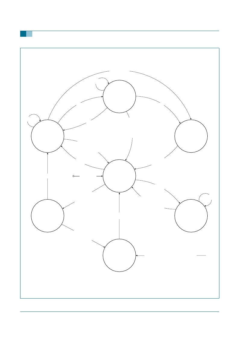
Fig 3.
Main state diagram
001aad180
flash entry enabled (111/001/111 mode sequence)
OR mode change to Sleep with pending wake-up
OR watchdog not properly served
OR interrupt ignored
>
t
OR RSTN falling edge detected
OR V1 undervoltage detected
OR illegal Mode register code
wake-up detected with its wake-up interrupt disabled
OR mode change to Sleep with pending wake-up
OR watchdog time-out with watchdog timeout interrupt disabled
OR watchdog OFF and I
>
I
thH(V1)
with reset option
OR interrupt ignored
OR RSTN falling edge detected
OR V1 undervoltage detected
OR illegal Mode register code
Start-up mode
V1: ON
SYSINH: HIGH
CAN: on-line/on-line listen/off-line
LIN: off-line
watchdog: start-up
INH/LIMP: HIGH/LOW/float
EN: LOW
Restart mode
V1: ON
SYSINH: HIGH
CAN: on-line/on-line listen/off-line
LIN: off-line
watchdog: start-up
INH/LIMP: LOW/float
EN: LOW
Sleep mode
V1: OFF
SYSINH: HIGH/float
CAN: on-line/on-line listen/off-line
LIN: off-line
watchdog: time-out/OFF
INH/LIMP: LOW/float
RSTN: LOW
EN: LOW
Fail-safe mode
V1: OFF
SYSINH: HIGH/float
CAN: on-line/on-line listen/off-line
LIN: off-line
watchdog: OFF
INH/LIMP: LOW
RSTN: LOW
EN: LOW
Normal mode
V1: ON
SYSINH: HIGH
CAN: all modes available
LIN: all modes available
watchdog: window
INH/LIMP: HIGH/LOW/float
EN: HIGH/LOW
Flash mode
V1: ON
SYSINH: HIGH
CAN: all modes available
LIN: all modes available
watchdog: time-out/OFF
INH/LIMP: HIGH/LOW/float
EN: HIGH/LOW
Standby mode
V1: ON
SYSINH: HIGH
CAN: on-line/on-line listen/off-line
LIN: off-line
watchdog: time-out/OFF
INH/LIMP: HIGH/LOW/float
EN: HIGH/LOW
mode change via SPI
mode change via SPI
mode change via SPI
Owake-up detected
OR V3 overload detected
wake-up detected
AND oscillator ok
AND t
t
ret
t
>
t
WD(init)
OR SPI clock count
16
OR RSTOR RSTN falling edge detected
OR illegal Mode register code
t
>
t
OR SPI clock count
16
OR RSTN falling edge detected
OR RSTNOR illegal Mode register code
leave Flash mode code
OR watchdog time-out
OR RSTN falling edge detected
>
t
RSTN(INT)
OR V1 undervoltage detected
OR illegal Mode register code
init Flash mode via SPI
init Normal mode
via SPI successful
init Normal mode
via SPI successful
supply connected
for the first time
from any
mode
oscillator fail
OR RSTN externally clamped HIGH detected
>
t
RSTN(CHT)
OR RSTN externally clamped LOW detected
>
t
RSTN(CLT)
OR RSTN released and V1 undervoltage detected
t
V1(CLT)
watchdog
trigger
watchdog
trigger
mode change via SPI
watchdog
trigger
相關PDF資料 |
PDF描述 |
|---|---|
| UL631H256 | SimtekLow Voltage SoftStore 32K x 8 nvSRAM |
| UL631H256S2C35 | SimtekLow Voltage SoftStore 32K x 8 nvSRAM |
| UL631H256S2C35G1 | SimtekLow Voltage SoftStore 32K x 8 nvSRAM |
| UL631H256S2C45 | SimtekLow Voltage SoftStore 32K x 8 nvSRAM |
| UL631H256S2K35 | SimtekLow Voltage SoftStore 32K x 8 nvSRAM |
相關代理商/技術參數 |
參數描述 |
|---|---|
| UJA1065TW | 制造商:PHILIPS 制造商全稱:NXP Semiconductors 功能描述:High-speed CAN/LIN fail-safe system basis chip |
| UJA1065TW/3V0 | 功能描述:網絡控制器與處理器 IC HI SPEED CAN SYSTEM RoHS:否 制造商:Micrel 產品:Controller Area Network (CAN) 收發器數量: 數據速率: 電源電流(最大值):595 mA 最大工作溫度:+ 85 C 安裝風格:SMD/SMT 封裝 / 箱體:PBGA-400 封裝:Tray |
| UJA1065TW/3V0,512 | 功能描述:CAN 接口集成電路 HI SPEED CAN SYSTEM RoHS:否 制造商:Texas Instruments 類型:Transceivers 工作電源電壓:5 V 電源電流: 工作溫度范圍:- 40 C to + 85 C 封裝 / 箱體:SOIC-8 封裝:Tube |
| UJA1065TW/3V0,518 | 功能描述:網絡控制器與處理器 IC HI SPEED CAN SYSTEM RoHS:否 制造商:Micrel 產品:Controller Area Network (CAN) 收發器數量: 數據速率: 電源電流(最大值):595 mA 最大工作溫度:+ 85 C 安裝風格:SMD/SMT 封裝 / 箱體:PBGA-400 封裝:Tray |
| UJA1065TW/3V0512 | 制造商:NXP Semiconductors 功能描述:CONTROLLER SYS CAN/LIN 3V 32HTSSOP |
發布緊急采購,3分鐘左右您將得到回復。