- 您現(xiàn)在的位置:買賣IC網(wǎng) > PDF目錄385311 > GS1559-CBE2 (Gennum Corporation) GS1559 HD-LINX-TM II Multi-Rate Deserializer with Loop-Through Cable Driver PDF資料下載
參數(shù)資料
| 型號: | GS1559-CBE2 |
| 廠商: | Gennum Corporation |
| 英文描述: | GS1559 HD-LINX-TM II Multi-Rate Deserializer with Loop-Through Cable Driver |
| 中文描述: | GS1559的HD - LINX進程,商標第二多速率解串器與環(huán)通電纜驅(qū)動器 |
| 文件頁數(shù): | 19/74頁 |
| 文件大小: | 686K |
| 代理商: | GS1559-CBE2 |
第1頁第2頁第3頁第4頁第5頁第6頁第7頁第8頁第9頁第10頁第11頁第12頁第13頁第14頁第15頁第16頁第17頁第18頁當前第19頁第20頁第21頁第22頁第23頁第24頁第25頁第26頁第27頁第28頁第29頁第30頁第31頁第32頁第33頁第34頁第35頁第36頁第37頁第38頁第39頁第40頁第41頁第42頁第43頁第44頁第45頁第46頁第47頁第48頁第49頁第50頁第51頁第52頁第53頁第54頁第55頁第56頁第57頁第58頁第59頁第60頁第61頁第62頁第63頁第64頁第65頁第66頁第67頁第68頁第69頁第70頁第71頁第72頁第73頁第74頁
GS1559 Data Sheet
30572 - 4
July 2005
19 of 74
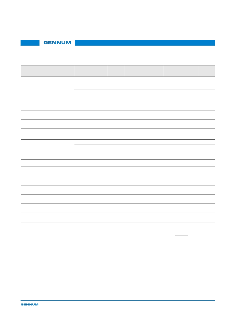
Serial Output Intrinsic
Jitter
t
IJ
Pseudorandom and
pathological HD
signal
–
90
125
ps
5
3
Pseudorandom and
pathological SD
signal
–
270
350
ps
5
3
Parallel Output
Parallel Clock
Frequency
f
PCLK
–
13.5
–
148.5
MHz
4
–
Parallel Clock Duty
Cycle
DC
PCLK
–
40
50
60
%
4
–
Output Data Hold
Time
t
OH
20-bit HD, 15pF
1.0
–
–
ns
4
–
10-bit SD, 15pF
19.5
–
–
ns
8
–
Output Data Delay
Time
t
OD
20-bit HD, 15pF
–
–
4.5
ns
4
–
10-bit SD, 15pF
–
–
22.8
ns
8
–
Output Data Rise/Fall
Time
tr/tf
–
–
–
1.5
ns
3
–
GSPI
GSPI Input Clock
Frequency
f
SCLK
–
–
–
6.6
MHz
8
–
GSPI Input Clock Duty
Cycle
DC
SCLK
–
40
–
60
%
8
–
GSPI Input Data
Setup Time
–
–
0
–
–
ns
8
–
GSPI Input Data Hold
Time
–
–
1.43
–
–
ns
8
–
GSPI Output Data
Hold Time
–
–
2.1
–
–
ns
8
–
GSPI Output Data
Delay Time
–
–
–
–
7.27
ns
8
–
TEST LEVELS
1. Production test at room temperature and nominal supply voltage with
guardbands for supply and temperature ranges.
2. Production test at room temperature and nominal supply voltage with
guardbands for supply and temperature ranges using correlated test.
3. Production test at room temperature and nominal supply voltage.
4. QA sample test.
5. Calculated result based on Level 1, 2, or 3.
6. Not tested. Guaranteed by design simulations.
7. Not tested. Based on characterization of nominal parts.
8. Not tested. Based on existing design/characterization data of similar
product.
9. Indirect test.
NOTES
1. 6MHz sinewave modulation.
2. HD = 1080i, SD = 525i
3. Serial Digital Output Reclocked (
RC_BYP
= HIGH).
4. See
Device Reset on page 68
,
Figure 4-16
.
Table 2-2: AC Electrical Characteristics (Continued)
T
A
= 0°C to 70°C, unless otherwise shown
Parameter
Symbol
Conditions
Min
Typ
Max
Units
Test
Level
Notes
相關(guān)PDF資料 |
PDF描述 |
|---|---|
| GS2905 | 500mA CMOS LDO Voltage Regulator |
| GS2905X15 | 500mA CMOS LDO Voltage Regulator |
| GS2905X18 | 500mA CMOS LDO Voltage Regulator |
| GS2905X25 | 500mA CMOS LDO Voltage Regulator |
| GS2905X33 | 500mA CMOS LDO Voltage Regulator |
相關(guān)代理商/技術(shù)參數(shù) |
參數(shù)描述 |
|---|---|
| GS1560 | 制造商:GENNUM 制造商全稱:GENNUM 功能描述:HD-LINX II Voltage Controlled Oscillator |
| GS1560A | 制造商:Gennum Corporation 功能描述: |
| GS1560A_07 | 制造商:GENNUM 制造商全稱:GENNUM 功能描述:Dual-Rate Deserializer |
| GS1560A_09 | 制造商:GENNUM 制造商全稱:GENNUM 功能描述:HD-LINX II Dual-Rate Deserializer |
發(fā)布緊急采購,3分鐘左右您將得到回復(fù)。