- 您現在的位置:買賣IC網 > PDF目錄365968 > TSB12LV22PZP (Texas Instruments, Inc.) OHCI-Lynx PCI-BASED IEEE 1394 HOST CONTROLLER PDF資料下載
參數資料
| 型號: | TSB12LV22PZP |
| 廠商: | Texas Instruments, Inc. |
| 英文描述: | OHCI-Lynx PCI-BASED IEEE 1394 HOST CONTROLLER |
| 中文描述: | OHCI的山貓基于PCI的1394主控制器 |
| 文件頁數: | 94/106頁 |
| 文件大小: | 605K |
| 代理商: | TSB12LV22PZP |
第1頁第2頁第3頁第4頁第5頁第6頁第7頁第8頁第9頁第10頁第11頁第12頁第13頁第14頁第15頁第16頁第17頁第18頁第19頁第20頁第21頁第22頁第23頁第24頁第25頁第26頁第27頁第28頁第29頁第30頁第31頁第32頁第33頁第34頁第35頁第36頁第37頁第38頁第39頁第40頁第41頁第42頁第43頁第44頁第45頁第46頁第47頁第48頁第49頁第50頁第51頁第52頁第53頁第54頁第55頁第56頁第57頁第58頁第59頁第60頁第61頁第62頁第63頁第64頁第65頁第66頁第67頁第68頁第69頁第70頁第71頁第72頁第73頁第74頁第75頁第76頁第77頁第78頁第79頁第80頁第81頁第82頁第83頁第84頁第85頁第86頁第87頁第88頁第89頁第90頁第91頁第92頁第93頁當前第94頁第95頁第96頁第97頁第98頁第99頁第100頁第101頁第102頁第103頁第104頁第105頁第106頁
8
–
1
8 TSB12LV32/Phy Interface
This section provides an overview of the digital interface between a TSB12LV32 and a physical layer device
(Phy). The information that follows can be used as a guide through the process of connecting the
TSB12LV32 to a 1394 Phy. The part numbers referenced, the TSB41LV03A and the TSB12LV32, represent
the Texas Instruments implementation of the Phy (TSB41LV03A) and link (TSB12LV32) layers of the IEEE
1394-1995 and P1394a standards.
The specific details of how the TSB41LV03A device operates are not discussed in this document. Only those
parts that relate to the TSB12LV32 Phy interface are mentioned.
8.1
Principles of Operation
The TSB12LV32 is designed to operate with a Texas Instruments physical-layer device. The following
paragraphs describe the operation of the Phy-LLC interface assuming a TSB41LV03A Phy. The
TSB41LV03A is an IEEE 1394a three port cable transceiver/arbiter Phy capable of 400 Mbits/s speeds.
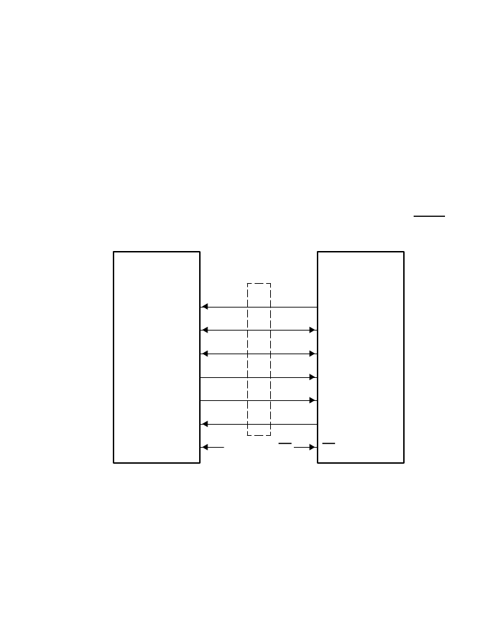
The interface to the Phy consists of the SCLK, CTL0
–
CTL1, D0
–
D7, LREQ, LPS, LINKON, and DIRECT
terminals on the TSB12LV32, as shown in Figure 8
–
1. Refer to Texas Instruments
Application Report
SLLA044
for a detailed description of the electrical interface between the TSB12LV32 and TSB41LV03.
TSB12LV32
Link-Layer
Controller
DIRECT
LINKON
LPS
SCLK
LREQ
D0
–
D7
CTL0
–
CTL1
TSB41LV03A
Physical-Layer
Device
ISO
C/LKON
LPS
SYSCLK
LREQ
D0
–
D7
CTL0
–
CTL1
ISO
DIRECT
Phy/LLC Interface
Figure 8
–
1. Phy-LLC Interface
The SYSCLK from the Phy terminal provides a 49.152 MHz interface clock. All control and data signals are
synchronized to, and sampled on, the rising edge of SYSCLK.
The CTL0 and CTL1 terminals form a bidirectional control bus, which controls the flow of information and
data between the TSB41LV03A and TSB12LV32.
The D0
–
D7 terminals form a bidirectional data bus, which is used to transfer status information, control
information, or packet data between the devices. The TSB41LV03A supports S100, S200, and S400 data
transfers over the D0
–
D7 data bus. In S100 operation only the D0 and D1 terminals are used; in S200
operation only the D0
–
D3 terminals are used; and in S400 operation all D0
–
D7 terminals are used for data
相關PDF資料 |
PDF描述 |
|---|---|
| TSB12LV26PZ | OHCI-Lynx PCI-BASED IEEE 1394 HOST CONTROLLER |
| TSB14AA1 | FPGA (Field-Programmable Gate Array) |
| TSB14AA1I | FPGA (Field-Programmable Gate Array) |
| TSB14AA1T | FPGA (Field-Programmable Gate Array) |
| TSB14C01MHV | IC APEX 20KE FPGA 160K 484-FBGA |
相關代理商/技術參數 |
參數描述 |
|---|---|
| TSB12LV23 | 制造商:TI 制造商全稱:Texas Instruments 功能描述:TSB12LV23 OHCI-Lynx PCI-Based IEEE 1394 Host Controller |
| TSB12LV23PZ | 制造商:TI 制造商全稱:Texas Instruments 功能描述:TSB12LV23 OHCI-Lynx PCI-Based IEEE 1394 Host Controller |
| TSB12LV26 | 制造商:TI 制造商全稱:Texas Instruments 功能描述:OHCI-Lynx PCI-BASED IEEE 1394 HOST CONTROLLER |
| TSB12LV26-EP | 制造商:未知廠家 制造商全稱:未知廠家 功能描述:Military Enhanced Plastic OHCI-Lynx PCI-Based IEEE 1394 Host Controller |
| TSB12LV26IPZT | 功能描述:1394 接口集成電路 OHCI-Lynx PCI-Based Host Controller RoHS:否 制造商:Texas Instruments 類型:Link Layer Controller 工作電源電壓: 封裝 / 箱體:LQFP 封裝:Tray |
發布緊急采購,3分鐘左右您將得到回復。