- 您現在的位置:買賣IC網 > PDF目錄379644 > ADC82124 (Electronic Theatre Controls, Inc.) 24 Ports 10/100 Fast Ethernet Switch Controller PDF資料下載
參數資料
| 型號: | ADC82124 |
| 廠商: | Electronic Theatre Controls, Inc. |
| 英文描述: | 24 Ports 10/100 Fast Ethernet Switch Controller |
| 中文描述: | 24端口10/100快速以太網開關控制器 |
| 文件頁數: | 12/48頁 |
| 文件大小: | 411K |
| 代理商: | ADC82124 |
第1頁第2頁第3頁第4頁第5頁第6頁第7頁第8頁第9頁第10頁第11頁當前第12頁第13頁第14頁第15頁第16頁第17頁第18頁第19頁第20頁第21頁第22頁第23頁第24頁第25頁第26頁第27頁第28頁第29頁第30頁第31頁第32頁第33頁第34頁第35頁第36頁第37頁第38頁第39頁第40頁第41頁第42頁第43頁第44頁第45頁第46頁第47頁第48頁
12
A
I
D
Prior to any transaction, the ACD82124 will output
thirty-two bits of ‘1’ as a preamble signal. After the
preamble, a ‘01’ signal is used to indicate the start of
the frame.
For a write operation, the device will send a ‘01’ to
signal a write operation. Following the ‘01’ write signal
will be the 5 bit ID address of the PHY device and the
5 bit register address. A ‘10’ turn around signal is then
followed. After the turn around, the 16 bit of data will
be written into the register. After the completion of the
write transaction, the line will be left in a high imped-
ance state.
For a read operation, the ACD82124 will output a ‘10’
to indicate read operation after the start of frame indi-
cator. Following the ‘10’ read signal will be the 5-bit ID
address of the PHY device and the 5-bit register ad-
dress. Then, the ACD82124 will cease driving the MDIO
line, and wait for one BT. During this time, the MDIO
should be in a high impedance state. The ACD82124
will then synchronize with the next bit of ‘0’ driven by
the PHY device, and continue on to read 16 bits of
data from the PHY device.
The system designer should set the ID of the PHY
devices as ‘1’ for port-0, ‘2’ for port-1, … and ‘24’ for
port-23. The detail timing requirement on PHY man-
agement signals are described in the chapter of “Tim-
ing Description.”
CPU Interface
The ACD82124 includes a CPU interface to enable an
external CPU to access the internal registers of the
ACD82124. The protocol used in the CPU is the asyn-
chronous serial signal (UART). The baud rate can be
from 1200 bps to 76800 bps. The ACD82124 auto-
matically detects the baud rate for each command,
and returns the result at the same baud rate. The sig-
nals in CPU interface are described in Table-6.5
A command sent by CPU comes through the CPUDI
line. The command consists of 9 octets. Command
frames transmitted on CPUDI have the following for-
mat (Table-6.6):
The byte order of data in all fields follows the big-endian
convention, i.e. most significant octet first. The bit or-
der is least significant order first. The Command octet
specifies the type of the operation. Bit 2 and bit 3 of
the command octet is used to specify the device ID of
the chip. They are set by bit 16 and bit 17 of the Reg-
ister 25 at power on strobing. The address octet speci-
fies the type of the register. The index octet specifies
the ID of the register in a register array. For write
operation, the Data field is a 4-octet value to specify
what to write into the register. For read operation, the
Data field is a 4-octet 0 as padded data. The checksum
value is an 8-bit value of exclusive-OR of all octets in
the frame, starting from the Command octet.
The ACD82124 will respond to each valid command
received by sending a response frame through the
CPUDO line. The response frames have the following
format (Table-6.7):
The command octet specifies the type of the response.
The result octet specifies the result of the execution.
The Result field in a response frame is defined as:
00 for no error
01 for Checksum
10 for address incorrect
11 for MDIO waiting time-out
For response to a read operation, the Data field is a 3-
octet value to indicate the content of the register. For
response to a write operation, the Data field is 24 bits
of 0. The checksum value is an 8-bit value of exclu-
sive-OR of all octets in the response frame, starting
from the Command octet.
Table-6.5: CPU Interface Signals
Name
Type
CPUDI
CPUDO
CPUIRQ
Description
CPU data input
CPU data output
CPU interrupt request
I
O
O
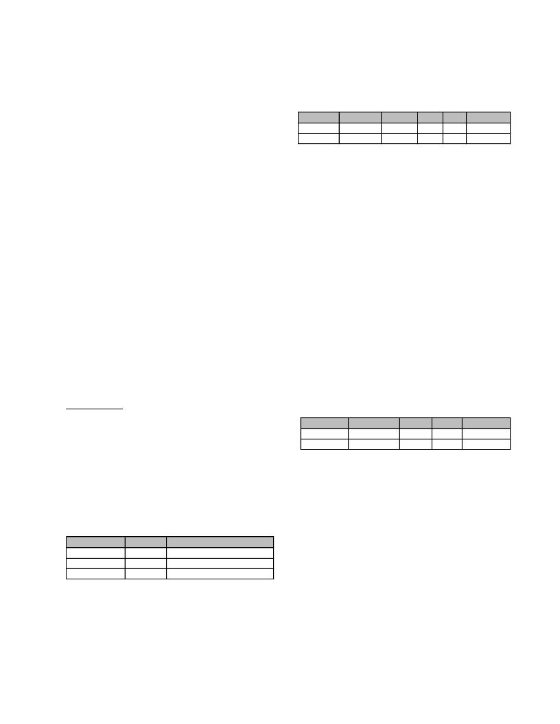
Table-6.7: Response Format
Response
Command
Write
00100011
Read
00100001
Result
8-bit
8-bit
Data
24-bit
24-bit
Checksum
8-bit
8-bit
Table-6.6: CPU Command Format
Operation Command Register Index Data Checksum
Write
0010XX11
8-bit
Read
0010XX01
8-bit
8-bit 24-bit
8-bit 24-bit
8-bit
8-bit
相關PDF資料 |
PDF描述 |
|---|---|
| ADEX-10L | Frequency Mixer Level 4 (LO Power +4 dBm) 10 to 1000 MHz |
| ADL-65055SA2 | Perfect Solution For Auto Power Controlled Laser Diode |
| ADM200 | Related Products: Motor Operated Auto Drain |
| ADM200-031- | Related Products: Motor Operated Auto Drain |
| ADM200-031-4 | Related Products: Motor Operated Auto Drain |
相關代理商/技術參數 |
參數描述 |
|---|---|
| ADC-825MC | 制造商:Murata Power Solutions 功能描述:Analog to Digital Converter |
| ADC-825MM | 制造商:Murata Power Solutions 功能描述:Analog to Digital Converter |
| ADC-826MC | 制造商:Murata Power Solutions 功能描述:Analog to Digital Converter |
| ADC-826MM | 制造商:未知廠家 制造商全稱:未知廠家 功能描述:Analog-to-Digital Converter, 10-Bit |
| ADC-827AMC | 制造商:Murata Power Solutions 功能描述:Analog to Digital Converter |
發布緊急采購,3分鐘左右您將得到回復。