- 您現(xiàn)在的位置:買賣IC網(wǎng) > PDF目錄98255 > TLV320DAC3120IRHBR (TEXAS INSTRUMENTS INC) SERIAL INPUT LOADING, 24-BIT DAC, PQCC32 PDF資料下載
參數(shù)資料
| 型號: | TLV320DAC3120IRHBR |
| 廠商: | TEXAS INSTRUMENTS INC |
| 元件分類: | DAC |
| 英文描述: | SERIAL INPUT LOADING, 24-BIT DAC, PQCC32 |
| 封裝: | 5 X 5 MM, PLASTIC, QFN-32 |
| 文件頁數(shù): | 35/110頁 |
| 文件大小: | 1230K |
| 代理商: | TLV320DAC3120IRHBR |
第1頁第2頁第3頁第4頁第5頁第6頁第7頁第8頁第9頁第10頁第11頁第12頁第13頁第14頁第15頁第16頁第17頁第18頁第19頁第20頁第21頁第22頁第23頁第24頁第25頁第26頁第27頁第28頁第29頁第30頁第31頁第32頁第33頁第34頁當(dāng)前第35頁第36頁第37頁第38頁第39頁第40頁第41頁第42頁第43頁第44頁第45頁第46頁第47頁第48頁第49頁第50頁第51頁第52頁第53頁第54頁第55頁第56頁第57頁第58頁第59頁第60頁第61頁第62頁第63頁第64頁第65頁第66頁第67頁第68頁第69頁第70頁第71頁第72頁第73頁第74頁第75頁第76頁第77頁第78頁第79頁第80頁第81頁第82頁第83頁第84頁第85頁第86頁第87頁第88頁第89頁第90頁第91頁第92頁第93頁第94頁第95頁第96頁第97頁第98頁第99頁第100頁第101頁第102頁第103頁第104頁第105頁第106頁第107頁第108頁第109頁第110頁
SLAS659 – NOVEMBER 2009
www.ti.com
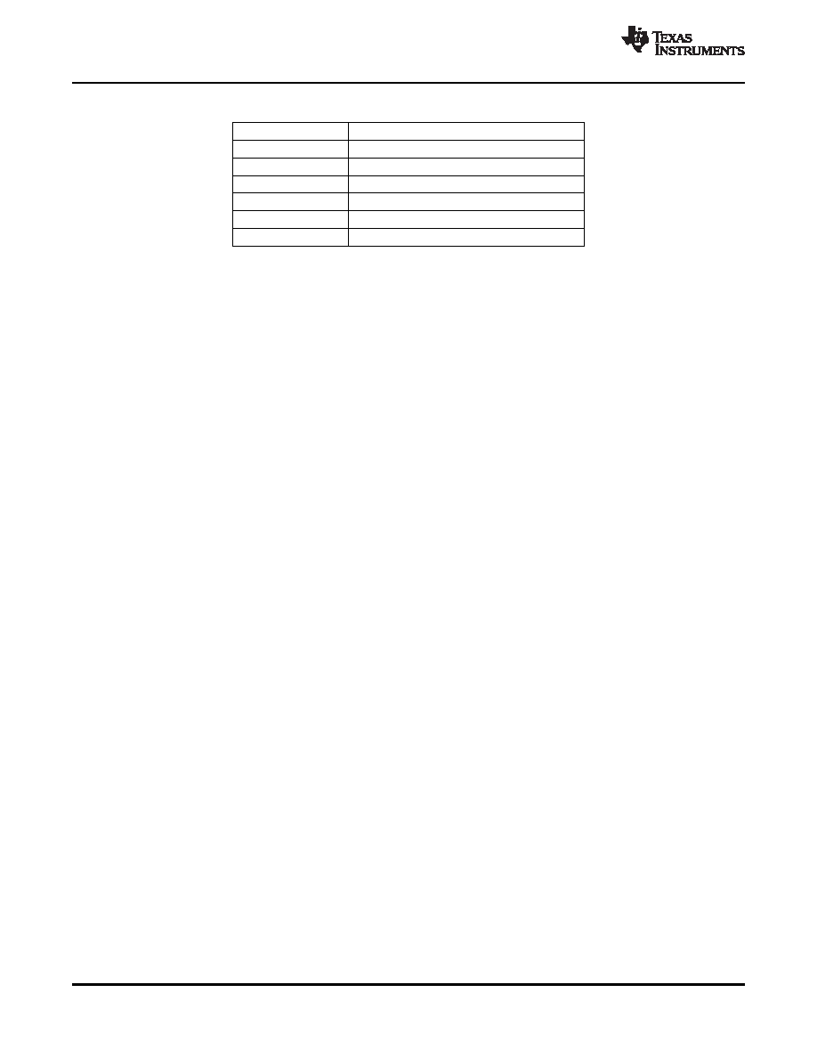
Table 5-15. DRC HPF and LPF Coefficients
Coefficient
Location
HPF N0
C71 page 9 / registers 14 to 15
HPF N1
C72 page 9 / registers 16 to 17
HPF D1
C73 page 9 / registers 18 to 19
LPF N0
C74 page 9 / registers 20 to 21
LPF N1
C75 page 9 / registers 22 to 23
LPF D1
C76 page 9 / registers 24 to 25
The default values of these coefficients implement a high-pass filter with a cutoff at 0.00166 × DAC_fS,
and a low-pass filter with a cutoff at 0.00033 × DAC_fS.
The output of the DRC high-pass filter is fed to the processing block selected for the DAC channel. The
absolute value of the DRC-LPF filter is used for energy estimation within the DRC.
The gain in the DAC digital volume control is controlled by page 0 / registers 65 and 66. When the DRC is
enabled, the applied gain is a function of the digital volume-control register setting and the output of the
DRC.
The DRC parameters are described in sections that follow.
5.6.4.1
DRC Threshold
The DRC threshold represents the level of the DAC playback signal at which the gain compression
becomes active. The output of the digital volume control in the DAC is compared with the set threshold.
The threshold value is programmable by writing to page 0 / register 68, bits D4–D2. The threshold value
can be adjusted between –3 dBFS and –24 dBFS in steps of 3 dB. Keeping the DRC threshold value too
high may not leave enough time for the DRC block to detect peaking signals, and can cause excessive
distortion at the outputs. Keeping the DRC threshold value too low can limit the perceived loudness of the
output signal.
The recommended DRC threshold value is –24 dB.
When the output signal exceeds the set DRC threshold, the interrupt flag bits at page 0 / register 44,
bits D3–D2 are updated. These flag bits are sticky in nature, and are reset only after they are read back
by the user. The non-sticky versions of the interrupt flags are also available at page 0 / register 46, bits
D3–D2.
5.6.4.2
DRC Hysteresis
DRC hysteresis is programmable by writing to page 0 / register 68, bits D1–D0. These bits can be
programmed to represent values between 0 dB and 3 dB in steps of 1 dB. It is a programmable window
around the programmed DRC threshold that must be exceeded for disabled DRC to become enabled, or
enabled DRC to become disabled. For example, if the DRC threshold is set to –12 dBFS and the DRC
hysteresis is set to 3 dB, then if the gain compression in DRC is inactive, the output of the DAC digital
volume control must exceed –9 dBFS before gain compression due to the DRC is activated. Similarly,
when the gain compression in the DRC is active, the output of the DAC digital volume control must fall
below –15 dBFS for gain compression in the DRC to be deactivated. The DRC hysteresis feature prevents
the rapid activation and de-activation of gain compression in DRC in cases when the output of the DAC
digital volume control rapidly fluctuates in a narrow region around the programmed DRC threshold. By
programming the DRC hysteresis as 0 dB, the hysteresis action is disabled.
The recommended value of DRC hysteresis is 3 dB.
30
APPLICATION INFORMATION
Copyright 2009, Texas Instruments Incorporated
Product Folder Link(s): TLV320DAC3120
相關(guān)PDF資料 |
PDF描述 |
|---|---|
| TLV320DAC3120IRHBT | SERIAL INPUT LOADING, 24-BIT DAC, PQCC32 |
| TLV320DAC3202IYZJR | VOLUME CONTROL CIRCUIT, PBGA20 |
| TLV320DAC3202IYZJT | VOLUME CONTROL CIRCUIT, PBGA20 |
| TLV320DAC32IRHBR | SERIAL INPUT LOADING, DAC WITH PROGRAMMABLE PLL, PQCC32 |
| TLV320DAC32IRHBTG4 | SERIAL INPUT LOADING, DAC WITH PROGRAMMABLE PLL, PQCC32 |
相關(guān)代理商/技術(shù)參數(shù) |
參數(shù)描述 |
|---|---|
| TLV320DAC3120IRHBT | 功能描述:音頻數(shù)/模轉(zhuǎn)換器 IC Lo-Pwr Audio DAC w/ Audio Proc RoHS:否 制造商:Texas Instruments 轉(zhuǎn)換器數(shù)量: 分辨率:16 bit 接口類型:I2S, UBS 轉(zhuǎn)換速率: 信噪比:98 dB 工作電源電壓:5 V DAC 輸出端數(shù)量:2 工作溫度范圍:- 25 C to + 85 C 電源電流:23 mA 安裝風(fēng)格:SMD/SMT 封裝 / 箱體:TQFP-32 封裝:Reel |
| TLV320DAC3120IRHBT | 制造商:Texas Instruments 功能描述:D/A Converter (D-A) IC 制造商:Texas Instruments 功能描述:IC, DAC, 32BIT, 192KSPS, QFN-32 |
| TLV320DAC32 | 制造商:BB 制造商全稱:BB 功能描述:LOW POWER STEREO AUDIO DAC FOR PORTABLE AUDIO/TELEPHONY |
| TLV320DAC3202 | 制造商:TI 制造商全稱:Texas Instruments 功能描述:LOW POWER HIGH FIDELITY I2S INPUT HEADSET IC |
| TLV320DAC3202BYZJR | 功能描述:音頻數(shù)/模轉(zhuǎn)換器 IC Lo Pwr Hi Fidelity I2S Input Headset IC RoHS:否 制造商:Texas Instruments 轉(zhuǎn)換器數(shù)量: 分辨率:16 bit 接口類型:I2S, UBS 轉(zhuǎn)換速率: 信噪比:98 dB 工作電源電壓:5 V DAC 輸出端數(shù)量:2 工作溫度范圍:- 25 C to + 85 C 電源電流:23 mA 安裝風(fēng)格:SMD/SMT 封裝 / 箱體:TQFP-32 封裝:Reel |
發(fā)布緊急采購,3分鐘左右您將得到回復(fù)。