- 您現在的位置:買賣IC網 > PDF目錄106304 > 11274-502-XTD PLL FREQUENCY SYNTHESIZER, 28 MHz, PDSO16 PDF資料下載
參數資料
| 型號: | 11274-502-XTD |
| 元件分類: | PLL合成/DDS/VCOs |
| 英文描述: | PLL FREQUENCY SYNTHESIZER, 28 MHz, PDSO16 |
| 封裝: | 0.150 INCH, GREEN, SOIC-16 |
| 文件頁數: | 11/40頁 |
| 文件大小: | 746K |
| 代理商: | 11274-502-XTD |
第1頁第2頁第3頁第4頁第5頁第6頁第7頁第8頁第9頁第10頁當前第11頁第12頁第13頁第14頁第15頁第16頁第17頁第18頁第19頁第20頁第21頁第22頁第23頁第24頁第25頁第26頁第27頁第28頁第29頁第30頁第31頁第32頁第33頁第34頁第35頁第36頁第37頁第38頁第39頁第40頁
19
AMI Semiconductor - Rev. 2.0, Jun. 05
www.amis.com
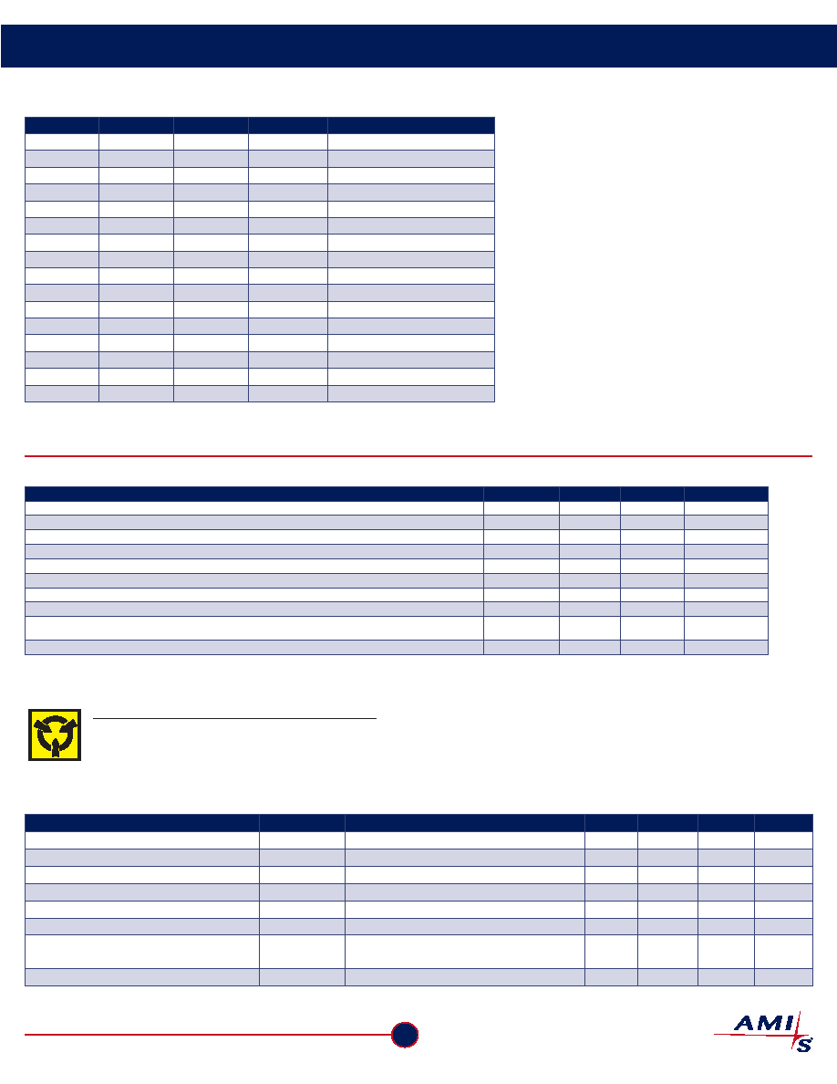
FS6131-01/FS6131-01g Programmable Line Lock Clock Generator IC
Data Sheet
Table 11: VCXO Coarse Running Capacitance
XCT[3]
XCT[2]
XCT[1]
XCT[0]
VCXO Tuning Capacitance (pf)
0
10.00
0
1
10.84
0
1
0
11.69
0
1
12.53
0
1
0
13.38
0
1
0
1
14.22
0
1
0
15.06
0
1
15.91
1
0
16.75
1
0
1
17.59
1
0
1
0
18.43
1
0
1
19.28
1
0
20.13
1
0
1
20.97
1
0
21.81
1
22.66
7.0 Electrical Specifications
Table 12: Absolute Maximum Ratings
Parameter
Symbol
Min.
Max.
Units
Supply voltage, dc (VSS = ground)
VDD
VSS-0.5
7
V
Input voltage, dc
Vl
VSS-0.5
VDD+0.5
V
Output voltage, dc
VO
VSS-0.5
VDD+0.5
V
Input clamp current, dc (VI < 0 or VI > VDD)
IIK
-50
50
mA
Output clamp current, dc (VI < 0 or VI > VDD)IOK
-50
50
mA
Storage temperature range (non-condensing)
TS
-65
150
°C
Ambient temperature range, under bias
TA
-55
125
°C
Junction temperature
TJ
150
°C
Re-flow solder profile
per IPC/JEDEC
J-STD-020B
Input static discharge voltage protection (MIL-STD 883E, Method 3015.7)
2
kV
Stresses above those listed under Absolute Maximum Ratings may cause permanent damage to the device. These conditions represent a stress rating only, and functional operation of
the device at these or any other conditions above the operational limits noted in this specification is not implied. Exposure to maximum rating conditions for extended conditions may
affect device performance, functionality and reliability.
CAUTION: ELECTROSTATIC SENSITIVE DEVICE
Permanent damage resulting in a loss of functionality or performance may occur if this device is subjected to a high-energy
electrostatic discharge.
Table 13: Operating Conditions
Parameter
Symbol
Conditions/Description
Min.
Typ.
Max.
Units
Supply voltage
VDD
5v ± 10%
4.5
5
5.5
V
Ambient operating temperature range
TA
0
70
°C
Crystal resonator frequency
fXIN
19.44
27
28
MHz
Crystal resonator load capacitance
CXL
Parallel resonant, AT cut
18
pF
Crystal resonator motional capacitance
CXM
Parallel resonant, AT cut
25
fF
Serial data transfer rate
Standard mode
10
100
400
kb/s
PECL mode programming current
(LOCK/IPRG pin high-level input current)
IIH
PECL mode
15
mA
Output driver load capacitance
CL
15
pF
相關PDF資料 |
PDF描述 |
|---|---|
| 15MV500 | 1-OUTPUT 1.25 W DC-DC UNREG PWR SUPPLY MODULE |
| 1025PE-42TE13 | 1-CHANNEL POWER SUPPLY SUPPORT CKT, PDIP8 |
| 1021ZD4E-28TE13 | 1-CHANNEL POWER SUPPLY MANAGEMENT CKT, DSO8 |
| 1025LI-45TE13 | 1-CHANNEL POWER SUPPLY SUPPORT CKT, PDIP8 |
| 12IWR1-05-05-NT | 2-OUTPUT 1 W DC-DC REG PWR SUPPLY MODULE |
相關代理商/技術參數 |
參數描述 |
|---|---|
| 1127-45-0516 | 制造商:Concord Electronics Inc 功能描述:Insulated Terminal 29.3mm 6.35mm Electro-Solder Over Copper |
| 1-1274574-0 | 制造商:TE Connectivity 功能描述:COMM BNC PLUG, LEAD FREE - Bulk |
| 112746 | 制造商:Amphenol Connex 功能描述: |
| 1127470000 | 功能描述:TOS 230VUC 230VAC1A 制造商:weidmuller 系列:* 零件狀態:有效 標準包裝:1 |
| 112747-HMC603MS10E | 制造商:Hittite Microwave Corp 功能描述:BOARD EVAL HMC603MS10E |
發布緊急采購,3分鐘左右您將得到回復。