- 您現在的位置:買賣IC網 > PDF目錄98255 > TLV320DAC3100IRHBT (TEXAS INSTRUMENTS INC) DAC WITH PROGRAMMABLE PLL, PQCC32 PDF資料下載
參數資料
| 型號: | TLV320DAC3100IRHBT |
| 廠商: | TEXAS INSTRUMENTS INC |
| 元件分類: | DAC |
| 英文描述: | DAC WITH PROGRAMMABLE PLL, PQCC32 |
| 封裝: | 5 X 5 MM, GREEN, PLASTIC, QFN-32 |
| 文件頁數: | 30/97頁 |
| 文件大小: | 1134K |
| 代理商: | TLV320DAC3100IRHBT |
第1頁第2頁第3頁第4頁第5頁第6頁第7頁第8頁第9頁第10頁第11頁第12頁第13頁第14頁第15頁第16頁第17頁第18頁第19頁第20頁第21頁第22頁第23頁第24頁第25頁第26頁第27頁第28頁第29頁當前第30頁第31頁第32頁第33頁第34頁第35頁第36頁第37頁第38頁第39頁第40頁第41頁第42頁第43頁第44頁第45頁第46頁第47頁第48頁第49頁第50頁第51頁第52頁第53頁第54頁第55頁第56頁第57頁第58頁第59頁第60頁第61頁第62頁第63頁第64頁第65頁第66頁第67頁第68頁第69頁第70頁第71頁第72頁第73頁第74頁第75頁第76頁第77頁第78頁第79頁第80頁第81頁第82頁第83頁第84頁第85頁第86頁第87頁第88頁第89頁第90頁第91頁第92頁第93頁第94頁第95頁第96頁第97頁
SLAS671 – FEBRUARY 2010
www.ti.com
This feature is enabled by programming page 0 / register 67, bit D1. In order to avoid false detections due
to mechanical vibrations in headset jacks or microphone buttons, a debounce function is provided for
glitch rejection. For the case of headset insertion, a debounce function with a range of 32 ms to 512 ms is
provided. This can be programmed via page 0 / register 67, bits D4–D2. For improved button-press
detection, the debounce function has a range of 8 ms to 32 ms by programming page 0 / register 67,
bits D1–D0.
The TLV320DAC3100 also provides feedback to the user through register-readable flags, as well as an
interrupt on the I/O pins when a button press or a headset insertion/removal event is detected. The value
in page 0 / register 46, bits D5–D4 provides the instantaneous state of button press and headset insertion.
Page 0 / register 44, bit D5 is a sticky (latched) flag that is set when the button-press event is detected.
Page 0 / register 44, bit D4 is a sticky flag which is set when the headset insertion or removal event is
detected. These sticky flags are set by the event occurrence, and are reset only when read. This requires
polling page 0 / register 44. To avoid polling and the associated overhead, the TLV320DAC3100 also
provides an interrupt feature, whereby events can trigger the INT1 and/or INT2 interrupts. These interrupt
events can be routed to one of the digital output pins. See Section 5.5.6 for details.
The TLV320DAC3101 not only detects a headset insertion event, but also is able to distinguish between
the different headsets inserted, such as stereo headphones or cellular headphones. After the
headset-detection event, the user can read page 0 / register 67, bits D6–D5 to determine the type of
headset inserted.
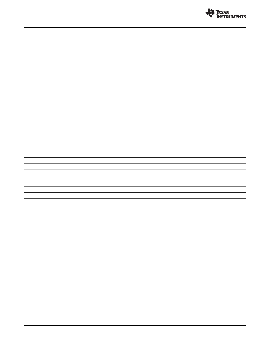
Table 5-21. Headset-Detection Block Registers
Register
Description
Page 0 / register 67, bits D4–D2
Debounce programmability for headset detection
Page 0 / register 67, bits D1–D0
Debounce programmability for button press
Page 0 / register 67, bits D6–D5
Flags for type of headset detected
Page 0/ register 46, bit D5
Status flag for button-press event
Page 0 / register 46, bit D4
Status flag for headset insertion and removal
Page 0 / register 44, bit D5
Sticky flag for button-press event
Page 0 / register 44, bit D4
Sticky flag for headset-insertion or -removal event
The headset detection block requires AVDD to be powered. The headset detection feature in the
TLV320DAC3101 is achieved with very low power overhead, requiring less than 20 mA of additional
current from the AVDD supply.
5.5.6
Interrupts
Some specific events in the TLV320DAC3100, which may require host processor intervention, can be
used to trigger interrupts to the host processor. This avoids polling the status-flag registers continuously.
The TLV320DAC3101 has two defined interrupts, INT1 and INT2, that can be configured by programming
page 0 / register 48 and page 0 / register 49. A user can configure interrupts INT1 and INT2 to be
triggered by one or many events, such as:
Headset detection
Button press
DAC DRC signal exceeding threshold
Overcurrent condition in headphone drivers/speaker drivers
Data overflow in the DAC processing blocks and filters
Each of these INT1 and INT2 interrupts can be routed to pin GPIO1. These interrupt signals can either be
configured as a single pulse or a series of pulses by programming page 0 / register 48, bit D0 and
page 0 / register 49, bit D0. If the user configures the interrupts as a series of pulses, the events trigger
the start of pulses that stop when the flag registers in page 0 / register 44 page 0 / register 45, and
page 0 / register 50 are read by the user to determine the cause of the interrupt.
36
APPLICATION INFORMATION
Copyright 2010, Texas Instruments Incorporated
Product Folder Link(s): TLV320DAC3100
相關PDF資料 |
PDF描述 |
|---|---|
| TLV320DAC3101IRHBT | DAC WITH PROGRAMMABLE PLL, PQCC32 |
| TLV320DAC3101IRHBR | DAC WITH PROGRAMMABLE PLL, PQCC32 |
| TLV320DAC3120IRHBR | SERIAL INPUT LOADING, 24-BIT DAC, PQCC32 |
| TLV320DAC3120IRHBT | SERIAL INPUT LOADING, 24-BIT DAC, PQCC32 |
| TLV320DAC3202IYZJR | VOLUME CONTROL CIRCUIT, PBGA20 |
相關代理商/技術參數 |
參數描述 |
|---|---|
| TLV320DAC3101 | 制造商:TI 制造商全稱:Texas Instruments 功能描述:Low-Power Stereo Audio DAC With Audio Processing and Stereo Class-D Speaker Amplifier |
| TLV320DAC3101EVM-U | 功能描述:音頻 IC 開發工具 TLV320DAC3101EVM-U Eval Mod RoHS:否 制造商:Texas Instruments 產品:Evaluation Kits 類型:Audio Amplifiers 工具用于評估:TAS5614L 工作電源電壓:12 V to 38 V |
| TLV320DAC3101IRHBR | 功能描述:音頻數/模轉換器 IC Low-Pwr audio DAC RoHS:否 制造商:Texas Instruments 轉換器數量: 分辨率:16 bit 接口類型:I2S, UBS 轉換速率: 信噪比:98 dB 工作電源電壓:5 V DAC 輸出端數量:2 工作溫度范圍:- 25 C to + 85 C 電源電流:23 mA 安裝風格:SMD/SMT 封裝 / 箱體:TQFP-32 封裝:Reel |
| TLV320DAC3101IRHBT | 功能描述:音頻數/模轉換器 IC Low-Pwr audio DAC RoHS:否 制造商:Texas Instruments 轉換器數量: 分辨率:16 bit 接口類型:I2S, UBS 轉換速率: 信噪比:98 dB 工作電源電壓:5 V DAC 輸出端數量:2 工作溫度范圍:- 25 C to + 85 C 電源電流:23 mA 安裝風格:SMD/SMT 封裝 / 箱體:TQFP-32 封裝:Reel |
| TLV320DAC3120 | 制造商:TI 制造商全稱:Texas Instruments 功能描述: |
發布緊急采購,3分鐘左右您將得到回復。