- 您現(xiàn)在的位置:買(mǎi)賣(mài)IC網(wǎng) > PDF目錄382738 > Z550 Telecomm/Datacomm PDF資料下載
參數(shù)資料
| 型號(hào): | Z550 |
| 元件分類(lèi): | 通信、網(wǎng)絡(luò)模塊及開(kāi)發(fā)工具 |
| 英文描述: | Telecomm/Datacomm |
| 中文描述: | 電信/數(shù)據(jù)通信 |
| 文件頁(yè)數(shù): | 8/30頁(yè) |
| 文件大小: | 581K |
| 代理商: | Z550 |
第1頁(yè)第2頁(yè)第3頁(yè)第4頁(yè)第5頁(yè)第6頁(yè)第7頁(yè)當(dāng)前第8頁(yè)第9頁(yè)第10頁(yè)第11頁(yè)第12頁(yè)第13頁(yè)第14頁(yè)第15頁(yè)第16頁(yè)第17頁(yè)第18頁(yè)第19頁(yè)第20頁(yè)第21頁(yè)第22頁(yè)第23頁(yè)第24頁(yè)第25頁(yè)第26頁(yè)第27頁(yè)第28頁(yè)第29頁(yè)第30頁(yè)
I
Z550 UART
I
––––––––––––––––––––––––––––––––––––––––––––––––––––––––––––––––––––––––––––––––––
8
Oki Semiconductor
Line Status Register
The Line Status Register (LSR) is a single register that provides status indications. The LSR is usually the
first register read by the CPU to determine the cause of an interrupt or to poll the status the serial channel.
The contents of the LSR is shown in
Figure 4
and described in the following table.
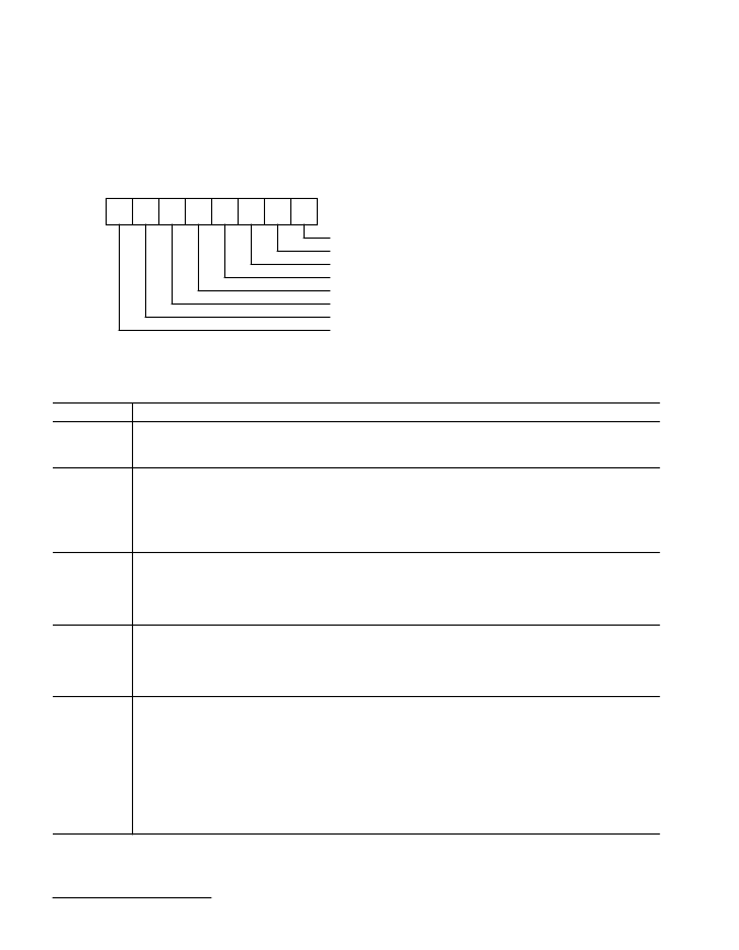
Figure 4. Line Status Register
Line Status Register Description
LSR Bit(s)
Description
LSR(0)
Data Ready (DR). Data Ready is set high when an incoming character has been received and transferred
into the Receiver Buffer Register. LSR(0) is reset low by a CPU read of the data in the Receiver Buffer Reg-
ister.
LSR(1)
Overrun Error (OE). Overrun Error indicates that data in the Receiver Buffer Register was not read by the
CPU before the next character was transferred into the Receiver Buffer Register, overwriting the previous
character. The OE indicator is reset whenever the CPU reads the contents of the Line Status Register.
An overrun error will occur in the FIFO Mode after the FIFO is full and the next character is completely re-
ceived. The overrun error is deleted by the CPU on the first LSR read after it happens. The character in the
shift register is not transferred to the FIFO but it is overwritten.
LSR(2)
Parity Error (PE). Parity Error indicates that the received data character does not have the correct parity, as
selected by LCR(3) and LCR(4). The PE bit is set high upon detection of a parity error, and is reset low when
the CPU reads the contents of the LSR.
In the FIFO Mode, the Parity Error is associated with a particular character in the FIFO. LCR(2) indicates the
error when the character is at the top of the FIFO.
LSR(3)
Framing Error (FE). Framing Error indicates that the received character did not have a valid stop bit. LSR(3)
is set high when the stop bit following the last data bit or parity bit is detected to be a logic “0” (spacing
level). The FE indicator is reset low when the CPU reads the contents of the LSR. In the FIFO Mode, the
Framing Error is associated with a particular character in the FIFO. LCR(3) indicates the error when the
character is at the top of the FIFO.
LSR(4)
Break Interrupt (BI). Break Interrupt is set high when the received data input is held in the spacing (logic
“0”) state for a full word transmission time (start bit + data bits + parity + stop bits). The BI indicator is reset
when the CPU reads the contents of the Line Status Register.
In the FIFO Mode, this is associated with a particular character in the FIFO. LCR(4) reflects the BI when the
break character is at the top of the FIFO. The error is deleted by the CPU when its associated character is
at the top of the FIFO during the first LSR read. Only one zero character is loaded into the FIFO when a BI
occurs.
LSR(1)-LSR(4) are the error conditions that produce a Receiver Line Status interrupt [priority 1 interrupt in
the Interrupt Identification Register (IIR)] when any of the conditions are detected. This interrupt is enabled
by setting IER(2)=1 in the Interrupt Enable Register.
LSR
7
LSR
6
LSR
5
LSR
4
LSR
3
LSR
2
LSR
1
LSR
0
Overrun Error (OE) (Error=1, No Error=0)
Parity Error (PE) (Error=1, No Error=0)
Framing Error (FE) (Error=1, No Error=0)
Break Interrupt (BI) (Break=1, No Break=0)
Transmitter Holding Register Empty (THRE) (Empty=1, Not Empty=0)
Transmitter Empty (TEMT) (Empty=1, Not Empty=0)
Receiver FIFO Error (Error in FIFO=1, No Error in FIFO=0)
Data Ready (DR) (Ready=1, Not Ready=0)
相關(guān)PDF資料 |
PDF描述 |
|---|---|
| Z5904 | Leaded Cartridge Fuse; Current Rating:1A; Voltage Rating:250V; Fuse Terminals:Axial Lead; Fuse Type:Time Delay; Body Material:Glass; Diameter:4.5mm; Fuse Size/Group:5 x 15 mm; Leaded Process Compatible:No; Length:14.48mm |
| Z6000(MLBA2) | FUSE,FAST ACTING,3A,250VAC |
| Z6005 | 3A 250V SLO-BLO NR 5X20MM |
| Z6006 | TANK SPRAY WASH |
| Z6011 | PCB PROCESSOR 3 SYSTEM |
相關(guān)代理商/技術(shù)參數(shù) |
參數(shù)描述 |
|---|---|
| Z550LA40A | 制造商:HVCA & CKE 功能描述:RADIAL LEAD MOV - LINE VOLTAGE - STANDARD ENERGY, 1500V, 50A, 180PF |
| Z550LA80A | 制造商:HVCA & CKE 功能描述:Varistor, MO; 910V; 6500A; 350pF |
| Z550MC10 | 制造商:OMRON AUTOMATION AND SAFETY 功能描述:Z550 SENSOR HEAD 制造商:OMRON Industrial Automation 功能描述:Z550 SENSOR HEAD |
| Z550-MC10 | 制造商:OMRON AUTOMATION AND SAFETY 功能描述:Z550 SENSOR HEAD 制造商:OMRON Industrial Automation 功能描述:Z550 SENSOR HEAD 制造商:OMRON INDUSTRIAL AUTOMATION 功能描述:Z550 Sensor Head |
| Z550MC15 | 制造商:OMRON AUTOMATION AND SAFETY 功能描述:Z550 SENSOR HEAD |
發(fā)布緊急采購(gòu),3分鐘左右您將得到回復(fù)。