- 您現在的位置:買賣IC網 > PDF目錄367493 > L84302 L84302 Quad 100/10 Mbps 4-Port Ethernet Controller with RMON/SNMP Management Counters technical manual 4/02 PDF資料下載
參數資料
| 型號: | L84302 |
| 元件分類: | 通用總線功能 |
| 英文描述: | L84302 Quad 100/10 Mbps 4-Port Ethernet Controller with RMON/SNMP Management Counters technical manual 4/02 |
| 中文描述: | L84302四100/10 Mbps的4端口以太網的遠程監控控制器/ SNMP管理處的技術手冊,4月2日 |
| 文件頁數: | 10/128頁 |
| 文件大小: | 997K |
| 代理商: | L84302 |
第1頁第2頁第3頁第4頁第5頁第6頁第7頁第8頁第9頁當前第10頁第11頁第12頁第13頁第14頁第15頁第16頁第17頁第18頁第19頁第20頁第21頁第22頁第23頁第24頁第25頁第26頁第27頁第28頁第29頁第30頁第31頁第32頁第33頁第34頁第35頁第36頁第37頁第38頁第39頁第40頁第41頁第42頁第43頁第44頁第45頁第46頁第47頁第48頁第49頁第50頁第51頁第52頁第53頁第54頁第55頁第56頁第57頁第58頁第59頁第60頁第61頁第62頁第63頁第64頁第65頁第66頁第67頁第68頁第69頁第70頁第71頁第72頁第73頁第74頁第75頁第76頁第77頁第78頁第79頁第80頁第81頁第82頁第83頁第84頁第85頁第86頁第87頁第88頁第89頁第90頁第91頁第92頁第93頁第94頁第95頁第96頁第97頁第98頁第99頁第100頁第101頁第102頁第103頁第104頁第105頁第106頁第107頁第108頁第109頁第110頁第111頁第112頁第113頁第114頁第115頁第116頁第117頁第118頁第119頁第120頁第121頁第122頁第123頁第124頁第125頁第126頁第127頁第128頁
10 of 128
April, 2002
L84302 Quad 4-Port Ethernet Controller - Technical Manual
Copyright 1997-2002 by LSI Logic Corporation. All rights reserved.
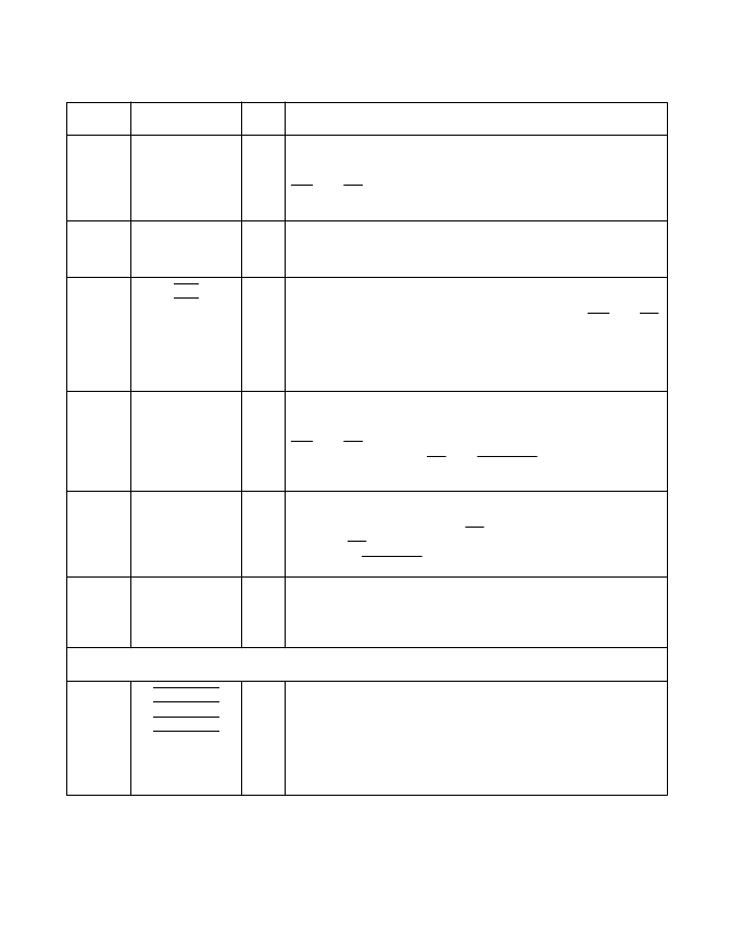
21 22 23
24 25 26
27 28
A[7:0]
I
Register Select Address Input.
These inputs provide the
address for the specific internal register to be accessed for a
selected port. These inputs are clocked in on falling edges of
WR and RD.
Note:
Pin #21 = A7, Pin # 28 = A0
18
BUSSIZE
I
Register Interface Bus Size Select.
1 = Register Interface Bus is 16 Bits Wide (CDST[15:0])
0 = Register Interface Bus is 8 Bits Wide (CDST[7:0])
14
13
BE1
BE0
I
Register Byte Enable Inputs.
These inputs determine which
bytes of the current 16-bit word on CDST[15:0] contain valid
data. The inputs are clocked in on falling edges of WR and RD.
11 = No Valid Data
10 = Valid data on CDST[7:0]
01 = Valid data on CDST[15:8]
00 = Valid data on CDST[15:0]
35 36 37
38 39 42
43 44 45
46 47 50
51 52 53
54
CDST[15:0]
I/O
Register Data Input.
This bidirectional bus is the 16-bit data
path to and from the internal registers for a selected port. Data
is read from/written to the internal registers on falling edges of
WR and RD. These pins are high impedance until their output
drivers are enabled by RD and ENREGIO being asserted low.
Note:
Pin #35 = CDST 15, Pin #54 = CDST 0
57
READY
O
Register Ready Indication Output.
This active high output
indicates that data being read out on CDST[15:0] is valid.
READY goes active high after RD has been asserted, and stays
high until RD is deasserted. READY goes into High Impedance
State when ENREGIO is deasserted.
34
33
32
31
INT_1
INT_2
INT_3
INT_4
O
Interrupt Output.
These outputs, one per port, are asserted
active high when certain interrupt bits are asserted. These pins
remain latched high until all interrupt bits causing the interrupt
condition are read.
Miscellaneous
174
197
220
243
FDUPLX_1
FDUPLX_2
FDUPLX_3
FDUPLX_4
I
Full Duplex Mode Input.
1 = Half Duplex
0 = Full Duplex
Full Duplex mode can also be selected by setting the Full
Duplex bit in the Configuration 2 register. Half-Duplex mode is
selected when both this pin and the Full Duplex mode bit are
set to Half Duplex.
Pin Description (Cont.)
Pin #
Pin Name
I/O
Description
相關PDF資料 |
PDF描述 |
|---|---|
| L8560 | Low-Power SLIC with Ringing |
| L8567 | SLIC for Peoples Republic of China Applications |
| L8567-32PLCC | Telecommunication IC |
| L8567-44PLCC | Telecommunication IC |
| L8574D | CAP 15PF 50V 5% C0G SMD-0402 TR-7-PA SN100 |
相關代理商/技術參數 |
參數描述 |
|---|---|
| L8446-04 | 制造商:HAMAMATSU 制造商全稱:Hamamatsu Corporation 功能描述:CW LASER DIODES |
| L8446-06 | 制造商:HAMAMATSU 制造商全稱:Hamamatsu Corporation 功能描述:CW LASER DIODES |
| L8446-07 | 制造商:HAMAMATSU 制造商全稱:Hamamatsu Corporation 功能描述:CW LASER DIODES |
| L8446-41 | 制造商:HAMAMATSU 制造商全稱:Hamamatsu Corporation 功能描述:CW LASER DIODES |
| L8446-42 | 制造商:HAMAMATSU 制造商全稱:Hamamatsu Corporation 功能描述:CW LASER DIODES |
發布緊急采購,3分鐘左右您將得到回復。