- 您現(xiàn)在的位置:買賣IC網(wǎng) > PDF目錄382347 > MR82510 (Intel Corp.) ASYNCHRONOUS SERIAL CONTROLLER PDF資料下載
參數(shù)資料
| 型號(hào): | MR82510 |
| 廠商: | Intel Corp. |
| 英文描述: | ASYNCHRONOUS SERIAL CONTROLLER |
| 中文描述: | 異步串行控制器 |
| 文件頁數(shù): | 10/40頁 |
| 文件大小: | 463K |
| 代理商: | MR82510 |
第1頁第2頁第3頁第4頁第5頁第6頁第7頁第8頁第9頁當(dāng)前第10頁第11頁第12頁第13頁第14頁第15頁第16頁第17頁第18頁第19頁第20頁第21頁第22頁第23頁第24頁第25頁第26頁第27頁第28頁第29頁第30頁第31頁第32頁第33頁第34頁第35頁第36頁第37頁第38頁第39頁第40頁
M82510
271072–10
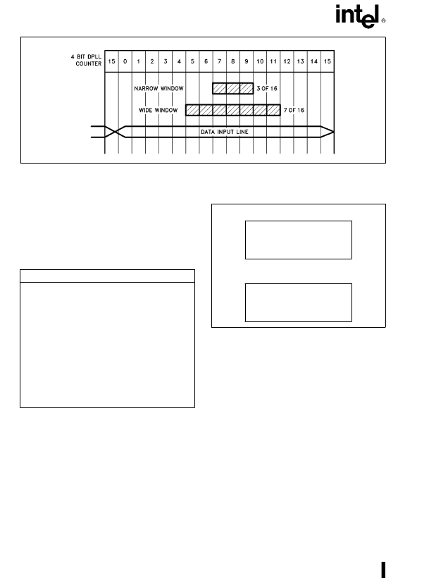
Figure 10. Sampling Windows
Control CharactersD
The Rx machine can gener-
ate a maskable interrupt upon reception of standard
ASCII or EBCDIC control characters, or an Address
marker is received in the uLAN mode. The Rx ma-
chine can also generate a maskable interrupt upon a
match with programmed characters in the Address/
Control Character 0 or Address/Control Character 1
registers.
Table 6. Control Character Recognition
CONTROL CHARACTER RECOGNITION
A
ó
STANDARD SET
X
ASCII:
000X XXXX
a
0111 1111
(ASCII DEL)
(00 - 1FH
a
7 FH)
OR
X
EBCDIC: 00XX XXXX
(00 - 3FH)
B
ó
User Programmed
X
ACR0, ACR1 XXXX XXXX
REGISTERS
Baud-Rate Generators/Timers
The M82510 has two-on-chip, 16-bit baud-rate gen-
erators. Each BRG can also be configured as a Tim-
er, and is completely independent of the other. This
can be used when the Transmit and Receive baud
rates are different. The mode, the output, and the
source of each BRG is configurable, and can also be
optionally output to external devices via the TA, TB
pins (see Figure 11. BRG Sources and Outputs).
SOFTWARE
CONTROLLED
GATE
Rx CLK
Tx CLK
BRGB
SOURCE
SYS CLK
XTAL CLK
SCLK
SOURCE
OUT
-A-
SOFTWARE
CONTROLLED
SCLK
SYS CLK
XTAL CLK
BRGA
OUTPUT
GATE
Rx CLK
Tx CLK
SOURCE
OUT
-B-
Figure 11. BRG Sources and Outputs
BAUD RATE GENERATION
The Baud Rate is generated by dividing the source
clock with the divisor count (from the Divisor count
registers). The count is loaded from the divisor count
registers into a count down register. A 50% duty cy-
cle is generated by counting down in steps of two.
When the count is down to 2 the entire count is re-
loaded and the output clock is toggled. Optionally
the two BRGs may be cascaded to provide a larger
divisor.
f
0
e
f
in
./Divisor
where
f
in is the input clock frequency and Divisor is
the count loaded into the appropriate count regis-
ters.
10
相關(guān)PDF資料 |
PDF描述 |
|---|---|
| MR8251A | PROGRAMMABLE COMMUNICATION INTERFACE |
| MR851G | Axial Lead Fast Recovery Rectifiers |
| MR851RL | Axial Lead Fast Recovery Rectifiers |
| MR851RLG | Axial Lead Fast Recovery Rectifiers |
| MR852G | Axial Lead Fast Recovery Rectifiers |
相關(guān)代理商/技術(shù)參數(shù) |
參數(shù)描述 |
|---|---|
| MR82510/B | 制造商:Rochester Electronics LLC 功能描述: |
| MR8251A | 制造商:Intel 功能描述: |
| MR8251A/B | 制造商:Rochester Electronics LLC 功能描述: |
| MR8254/B | 制造商:Rochester Electronics LLC 功能描述: |
| MR8254/R | 制造商:Rochester Electronics LLC 功能描述:- Bulk |
發(fā)布緊急采購,3分鐘左右您將得到回復(fù)。